During my time at Tesla working as a mechanical design engineer, I had a chance to design, prototype, source, and launch dozens of parts across the S/3/X/Y and Cybertruck platforms.
The great majority of these parts ensured comfortable safe cabin air for passengers.
Here are some high-level descriptions of the projects I took on.
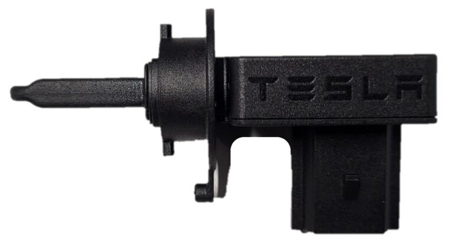
Relative Humidity / Temperature Sensor
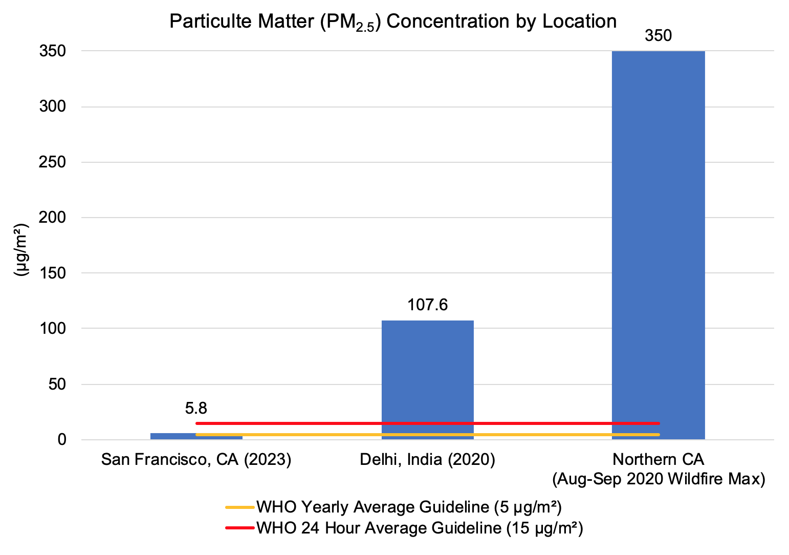
Atmospheric air pollution, or particulate matter (PM), is pollution suspended in the air and emitted from various natural (forest fires, volcanic eruption) and human activities (burning fossil fuels). The concentration of particulate matter is often used to quantify air pollution in a given area. PM2.5, or particles 2.5 μm and smaller are especially dangerous to people, as they can be inhaled into the lower respiratory system and eventually enter the bloodstream.
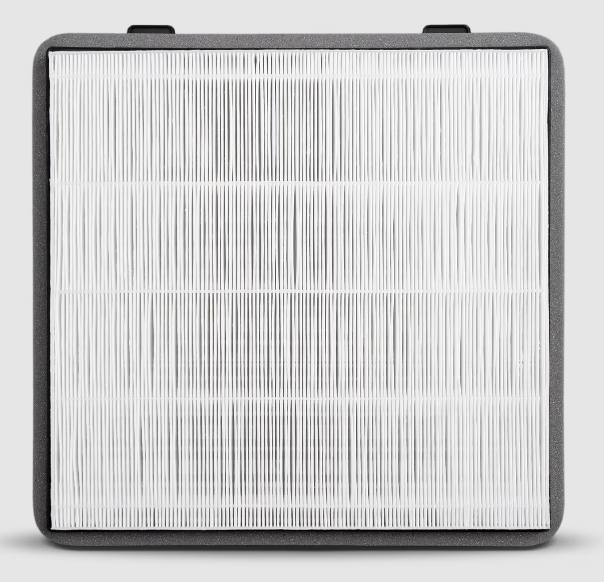
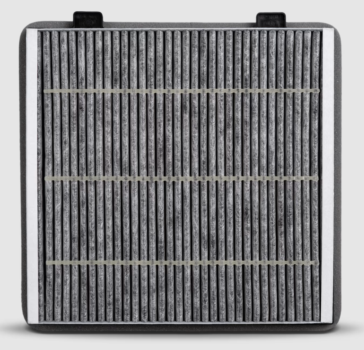
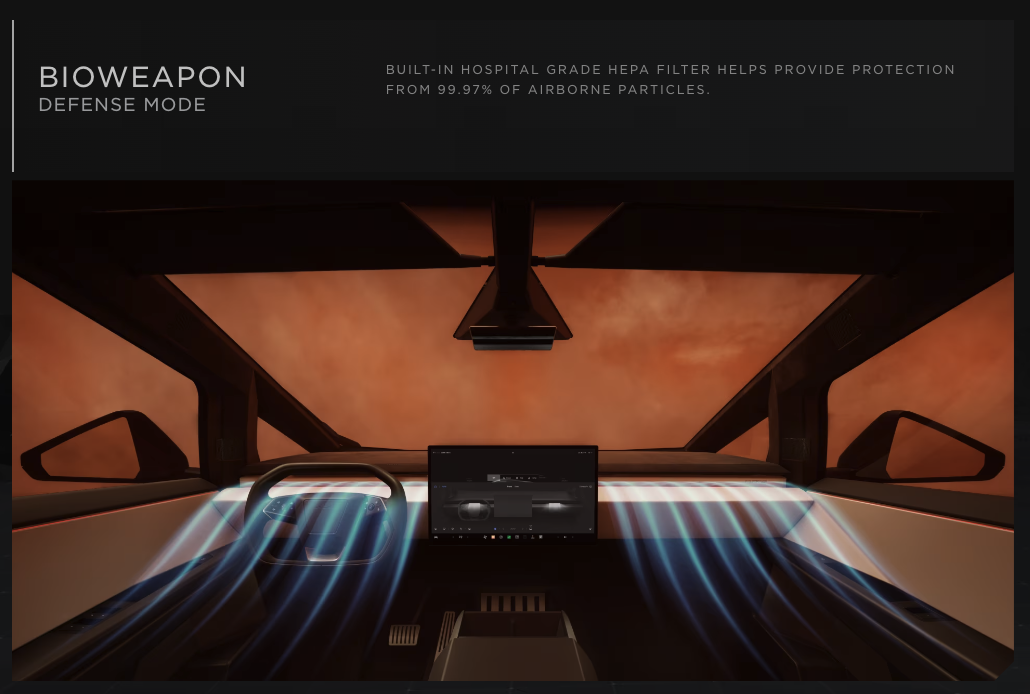
Following Cybertruck’s futuristic ‘overkill’ design aesthetic, we designed the cabin filter to adhere to HEPA filtration standards (99.97% efficiency at filtering airborne particles). This kind of filter would quickly filter the air inside the cabin and maintain very low PM concentrations in the face of highly polluted environments. In addition, I wrote a design standard to ensure the filter would filter odorous gases (common in swampy areas, livestock farms, and due to incomplete combustion) that would otherwise impact the occupant experience—e.g. NO2, SO2, H2S, NH3.
The main design constraints for this cabin filter are its pressure drop and the filtration efficiency. These are inversely related—by making the filter media more restrictive to particles and gases, the pressure drop across the filter generally increases. The HVAC blower works harder to push the same air volume through it. The pressure drop targets were set given the blower capacity and system performance targets, and serve as inputs for CFD simulation of the ducting and other HVAC functions.
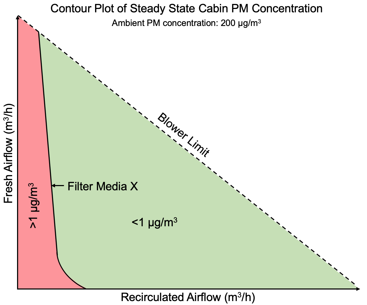
To determine the least restrictive filter media that would still meet the HEPA efficiency threshold, I wrote a MATLAB control volume analysis to determine the PM concentration in the truck cabin as a function of filter efficiency. The model accounts acconts for estimated body panel leakage rate, fresh/recirculated airflow ratios, and blower speeds. With only one filter in the truck, recirculating cabin air passes across the HEPA filter multiple times, giving us many chances to filter contaminants, getting us to a steady state PM concentration within a few minutes.
I defined ‘steady state’ as when the cabin PM concentration rate of change reached 5%.
With these values, I plotted the HVAC settings at which each supplier-proposed media would adhere to cabin safety standards (e.g. 1 ug/m3 at steady state).
The curves on resulting plots were used to understand how clean/safe the cabin air is at each HVAC blower speed and flow ratio. Ideally, the smaller the red area, the better. Below is a contour plot of how a particular media might perform. Low blower speeds push less air through the filter, removing fewer contaminants. With even a small fraction of fresh air, the blower can pressurize the cabin slightly, greatly reducing body leaks that carry contaminants.
The HEPA media I developed with our supplier ensured the cabin would adhere to HEPA cleanliness standards beginning at a low flow rate while falling under our pressure drop targets.
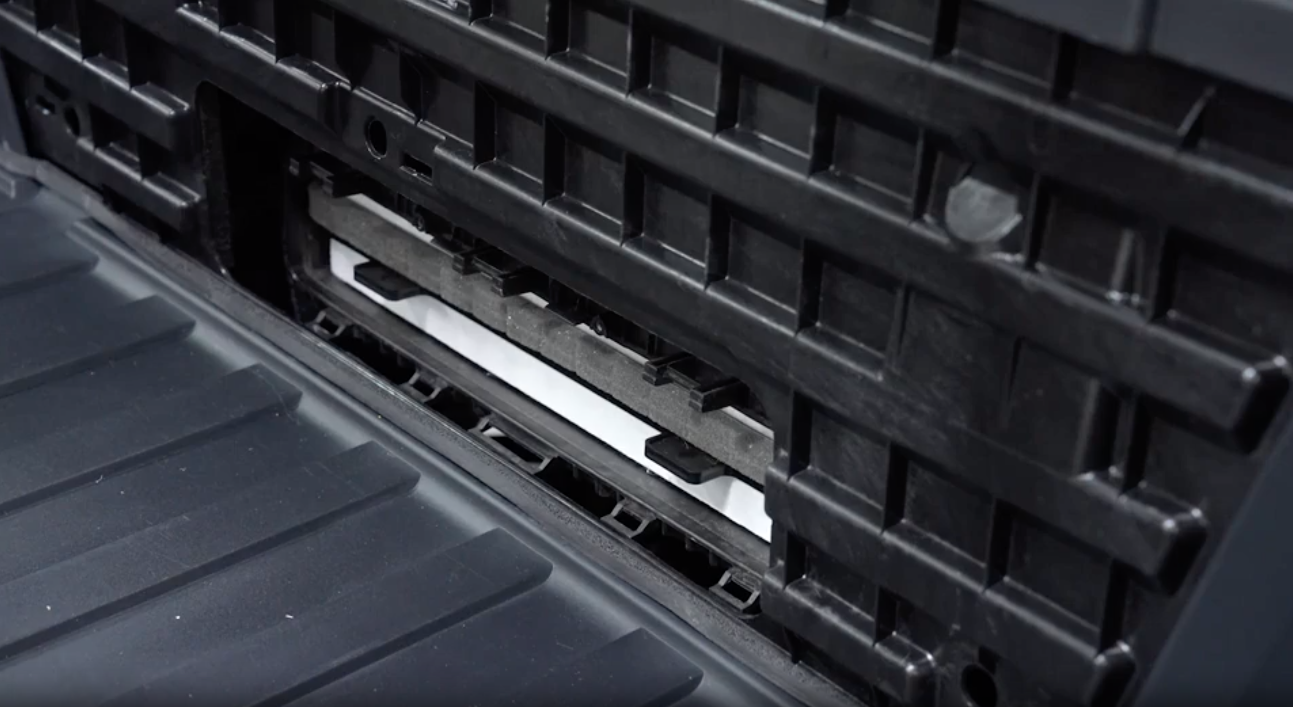
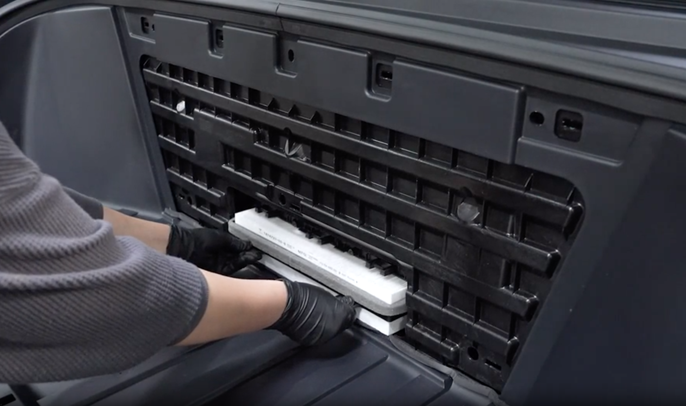
The Cybetruck HEPA filter is a fairly high-visibility feature enabling Tesla’s enhanced filtration mode, or Bioweapon Defense Mode. The filter and HVAC housing were positioned in the truck to be replaced easily without tools and without having to take apart much of the trim and instrument panel—the access port lives in the frunk (front trunk).
Sandy Munro talks briefly about this in his first impressions of the truck.
Before the release of the Cybertruck, vehicle programs used a fixed value for ambient air relative humidity in the HVAC firmware. This assumption, while effective in most cases, leaves energy savings on the table. For example, supposing the truck is in an arid environment at a cool temperature, the evaporator/condenser may unnecessarily heat and condense incoming air to remove moisture that isn’t present.
These thermal corner cases motivated me to investigate how much energy could be saved with a local relative humidity input from a sensor or API.
Gathering information about the fleet density across North America, and layering the daily and seasonal temperatures and humidities, I determined a weighted average of the fleet’s ambient air/HVAC load conditions. With a matrix of the potential HVAC energy savings at each temp and RH value, I determined the fleet average of the energy to be saved using a ‘real’ humidity value.
The estimated energy savings is equivalent to ~1.2 miles of range per charge. This energy-saving cost far exceeded the cost of adding this sensor. This figure supported my argument to source the part and have it included in the Cybertruck.
Roughly estimating, a fleet of 50,000 Cybertrucks each driving 10,000 miles/year, the sensor I designed would save roughly ~1 GWh, or the energy consumed by almost 100 US homes each year.
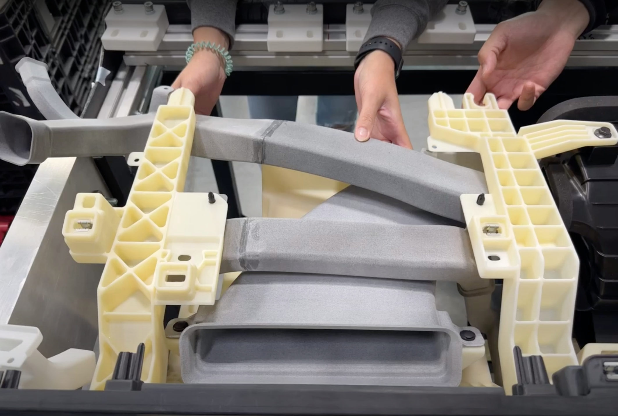
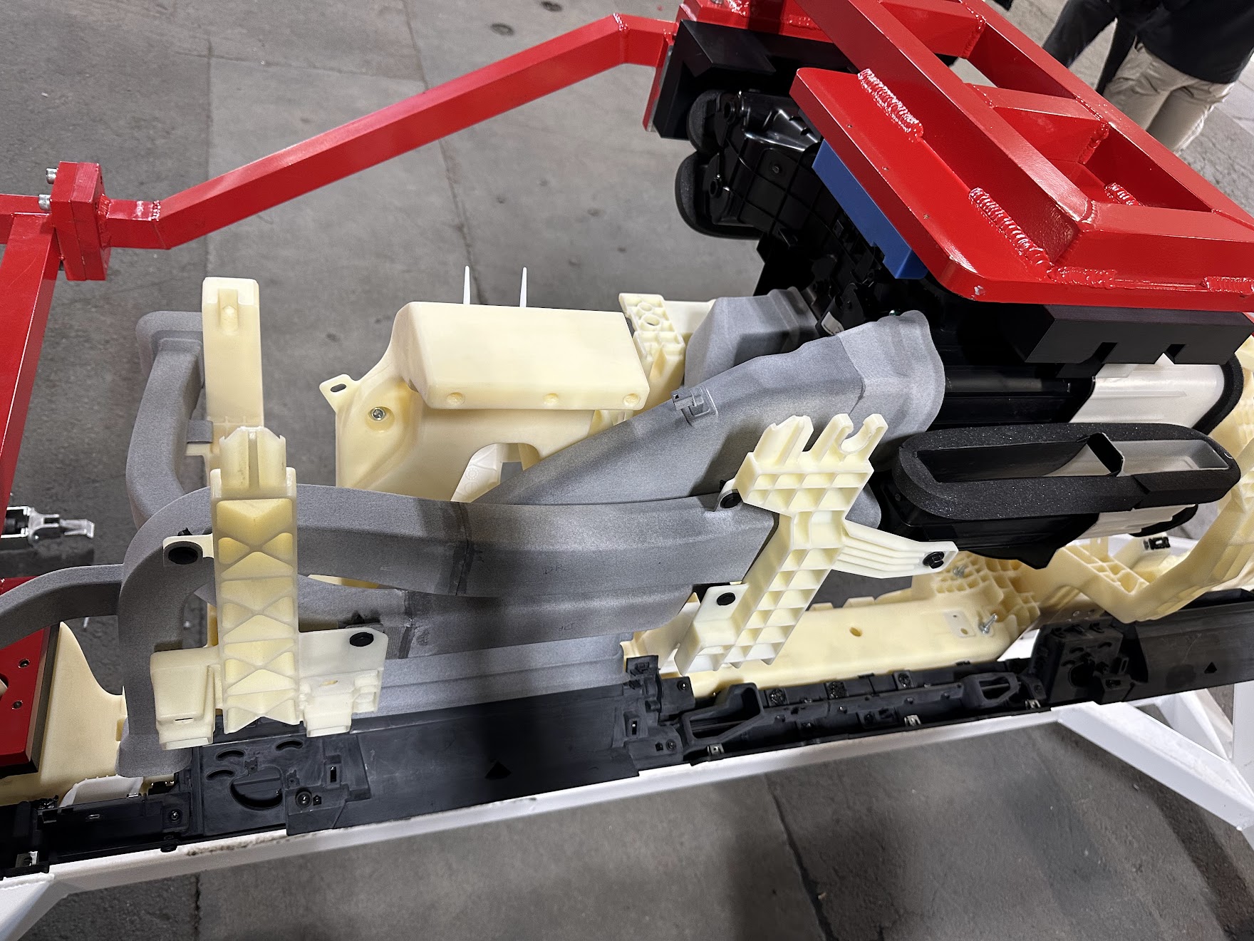
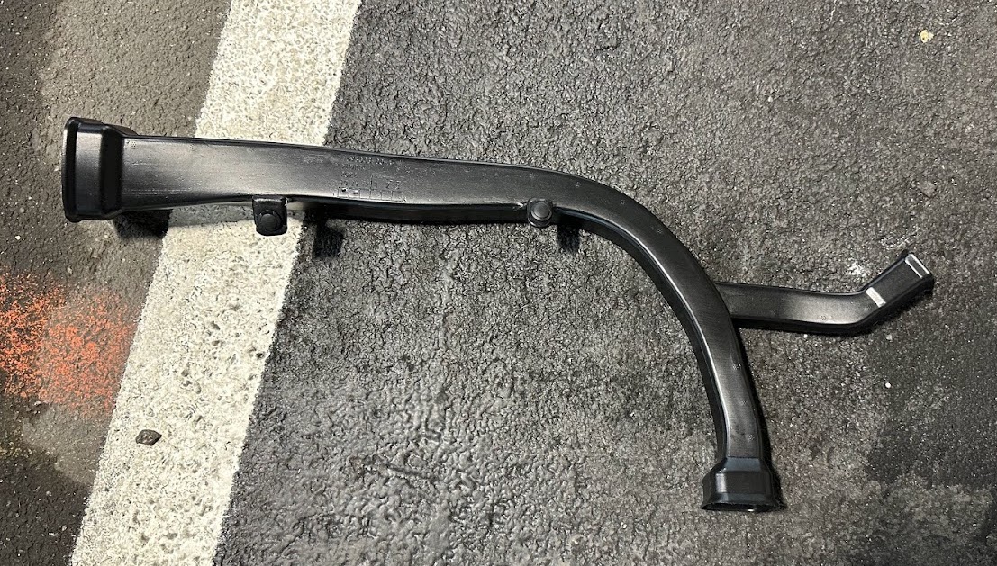
I designed, prototyped, and launched a few dozen air ducts while at Tesla. Used to move air from the HVAC to 1st, 2nd, and 3rd-row passengers, the plastic parts were designed with the unique constraints of blow molding in mind.
From an aerodynamic perspective, it's generally best to preserve the airflow characteristics (air velocity, pressure) through the ducting by limiting sharp corners, bends and changes in cross sections.
When designing long sections of ducting, the main challenge lies in simultaneously
• adhering to given packaging space, during and after installation
• creating robust locating features to fully locate the part once installed
• meeting tooling design requirements and
• preserving aerodynamic surfaces/attributes
Unlike injection molding, blow-molded parts are formed from a hot stretchy tube of plastic (the parison) that’s sealed by two halves of a metal mold and pressurized with air to create a hollow cavity. This manufacturing method has advantages (the finished part has no seams for air to leak through, relatively low capex) but has certain limitations. Being made of thin flexible plastic, the part’s expansion ratio (how the parison is made to expand in different directions) should be kept in mind to prevent holes/thin regions. Radii, locating features, parting lines, and undercuts also have their own design criteria, which is sometimes why blow molding is referred to jokingly as more of a ‘black art’ than science.
Deciding on locating schemes to control the form and fit of these parts (GD&T) was also a specific challenge as I designed most of these ducts from complex surfaces to maintain clearances and aerodynamic characteristics. Touch-off surfaces and pinned 4-way and 2-way locating features often served as datums to help check parts and inform manufacturing associates how they should be installed into the vehicle.
By the time the truck launched in 2023, I had designed/owned and launched 15 individual Cybertruck air ducts.
Early in the development cycle for ducting, filters, and other HVAC parts, my team would characterize new parts on test fixtures or entire test vehicles. Thermal comfort being fairly subjective, I would conduct thermal pulldown testing with the help of teammates to validate duct and outlet designs. This would involve ‘soaking’ the vehicle in a thermal chamber at high temperatures and humidity and asking passengers to rate their comfort and perceived temperature levels as the HVAC/ducting cooled off the cabin. Beyond the cooling power of the air carried from the evaporator to the passenger, the position and concision of air jets leaving ducting plays a role in passenger comfort. These comfort scores and comments were always helpful in fine-tuning duct designs before kicking off volume tooling.
UC Berkeley's Center for the Built Environment developed a helpful reference, the CBE Thermal Comfort Tool, used to help quantify thermal comfort.
Air quality and health impacts of the 2020 wildfires in California
UC Berkeley Center for the Build Environment, Thermal Comfort Tool