During my third year of undergrad I began biking across town to work with friends at Northeastern to help develop their Hyperloop race pod. Paradigm Hyperloop is a group of students from both the NEU and the Memorial University of Newfoundland that work together to prove the viability of the hyperloop as a high speed means of transporting people and goods.
The idea for the theoretical fifth means of transportation that is Hyperloop was first developed by Tesla and SpaceX engineers. It relies on hundreds of miles of tubes at incredibly low air pressures to allow for pods to travel at hundreds of miles per hour over relatively short distances (>1,500 km).
Beginning in 2016, SpaceX sponsored a design competition where student and non-student teams alike designed and built pods to race along a 1-mile-long sub-scale test track in Hawthorne, CA. Paradigm entered their pod to compete in the second year of competition in 2017, and proved to be fastest pod in North America and third fastest globally, reaching speeds over 60 mph. Our group is unique in being the first team to successfully implement air skates for the sake of levitation. By blowing compressed air through a series downwards facing holes, we can lift off from the test track, virtually eliminating contact friction and making near sonic travel possible.
Following the 2017 competition, when I got involved with the racing team, I was interested in further developing the levitation subassembly to be used in 2018’s competition. As the third Hyperloop competition would be judged primarily by top-speeds, we decided to scale down and to reorganize subsystems within our pod in order to reduce weight for maximum acceleration. As a part of this overhaul, we also set out to redesign our levitation subsystem. Instead of the cloth bags that were previously filled with air and used to slide along the test track, the new levitation assembly would feature skates alone to achieve total clearance from the ground.
Before building any physical models or prototypes, our sub-team worked to fully understand the dynamics and fluid mechanics involving levitation and acceleration in a near-vacuous travel environment. We began first with a rough drawing of the system we would later design with higher fidelity. We wanted to take advantage of incident air while moving to help create lift, so we designed a duct into the chassis to redirect air towards our pod’s air skates.
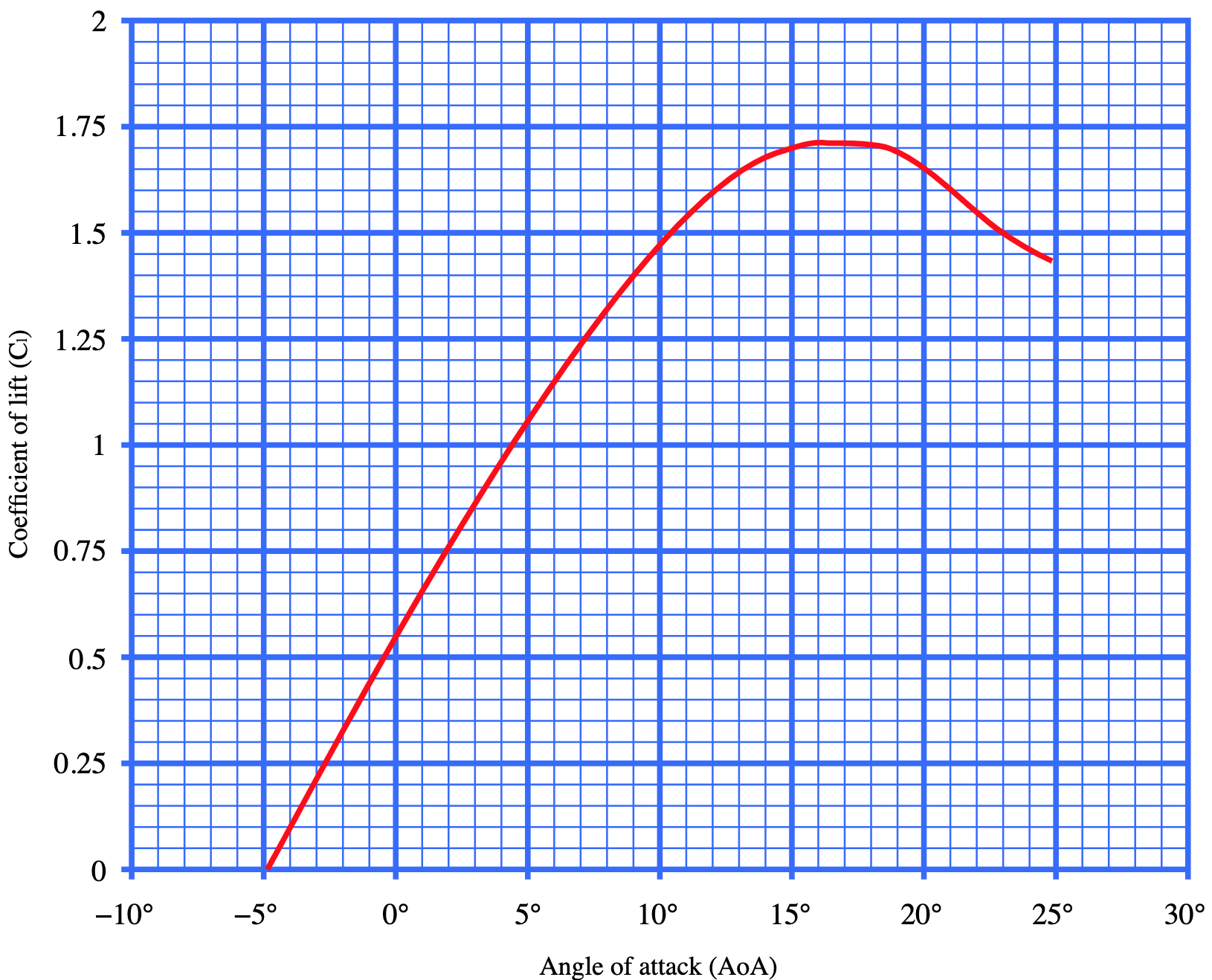
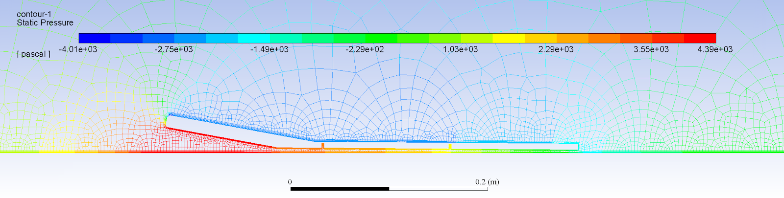
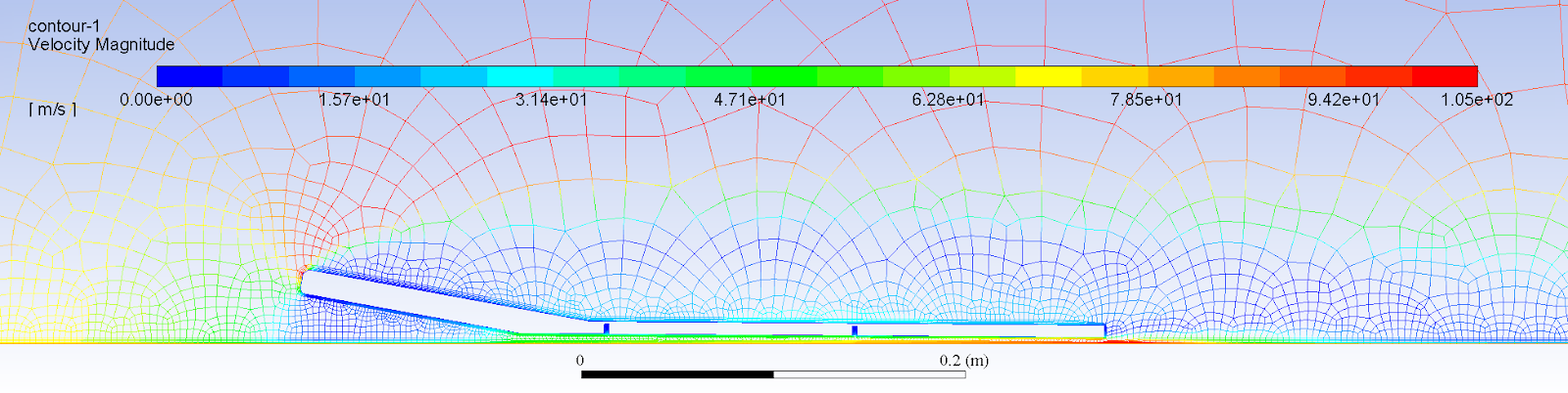
With a barebones design of the pod’s duct and air skate geometry, I calculated theoretical dynamic air pressure as a function of the distance from the duct’s opening. This mainly served as a sanity check for our higher-fidelity air skate FEA model, where air can actually escape the from the skates’ perimeter. With these, we were able to theoretically determine the lift/drag ratio of our designs given a few physical and aerodynamic parameters.
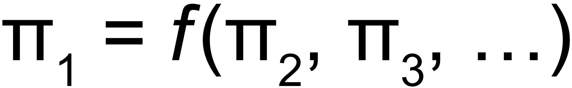
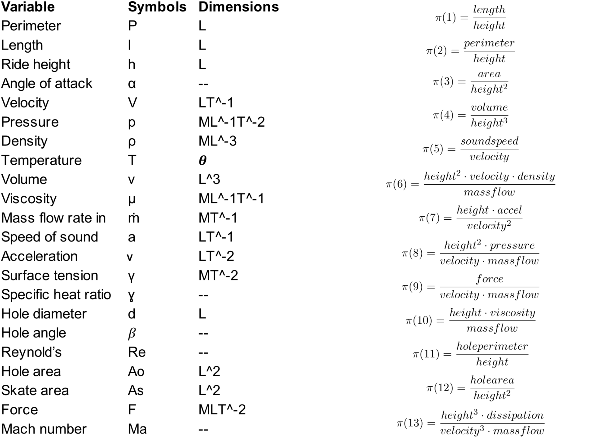
After some modeling we itemized all of the physical parameters that would affect the performance our the levitation subsystem, including the rate of airflow through the skates, the ride height of the skates, air viscosity, etc. Using the Buckingham Pi Theorem for the sake of dimensional analysis, we grouped these parameters into dimensionless ratios known as pi groups. We ranked these pi groups by how significant we thought they were to our system so that we could begin to experimentally determine their relationships to each another.
For example, pi group 6 (Fig. 7) is interesting because it relates parameters such as mass flow rate of air and air skate height. Airflow through the skates is a quantity that we can control relatively easily, and understanding its relationship to skate height (our main independent variable) is critical.
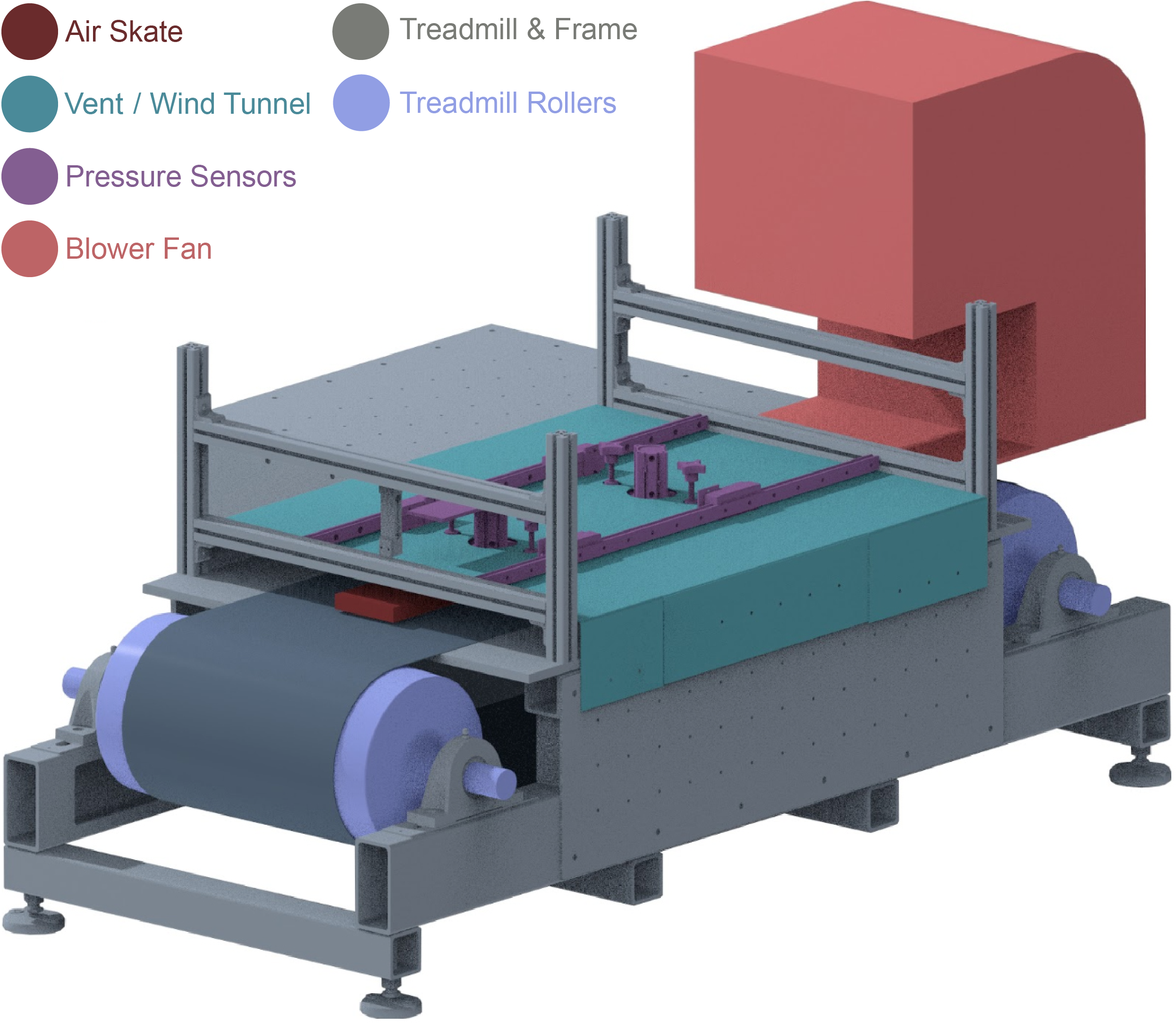
With groups of physical parameters a sense of how they might be related, I designed a vent assembly that would interface with an industrial blower to serve as a scaled down wind tunnel. We would use this assembly to begin measuring the dynamic characteristics of the air skate as function of various dependent variables, such as pressurized air flow rate, simulated pod velocity, etc.
We reached out to specialty treadmill company TuffTread to have a custom unit built to simulate the aerodynamic behavior that would occur when the air skate traveled along the test track. I designed the vent assembly to be fixed to this treadmill allowing us to tightly control qualities of incident air coming from the blower, including velocity and flow rate. Joining the air skate to the vent is a pressure sensor array, as well as other measuring devices to determine variables such as lift force and air skate ride height. All together, this model would help us understand and optimize our team’s levitation subassembly’s performance before building a full scale prototype for the race track.
Unfortunately, our team’s competition proposal was not selected by the review officials at SpaceX in charge of the hyperloop student competitions. The plans to continue building the scale and ultimately full sized air skates was put on hold as well. However, the next year’s team was able to continue reworking the successful 2017 pod design to go on to compete in the 2019 competition, winning 3rd in North America and 8th overall. The concept of air levitation continues to be investigated by a number of hyperloop teams and should hopefully prove to be a useful feature in pods of the future.