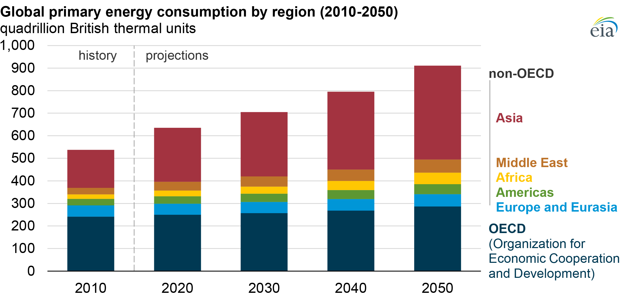
In 2019, the U.S. Energy Information Administration (EIA) projected that the global demand for electricity would increase by nearly 50% between 2018 and 2050. A large part of meeting this demand should come from the use of renewable resources, such as solar electricity, rather than the burning of fossil fuels. Two commonly cited shortcomings of current solar technology are inefficiency, as well as high initial costs.
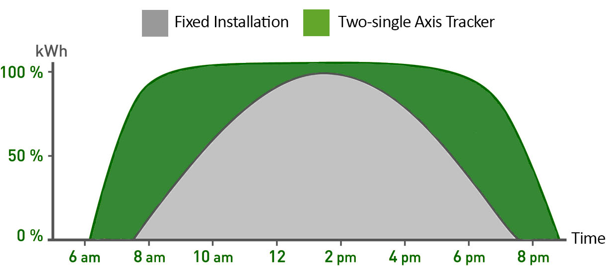
One type of solution proven to increase the returns on investment of solar panel arrays are devices known as solar trackers. These devices, both in research settings and commercially, have been used to increase the energy returns of photovoltaic cells (solar panels) by orienting them to follow the path of the sun throughout the course of the day.

A good deal of solar trackers involve closed loop control systems that minimize the discrepancy between solar irradiance (indicative of the direction of sunlight) and PV cell orientation. This solution requires electricity, which diminishes the returns made by active solar tracking.
Passive solar tracking solutions that rely on thermal expansion exist, and are available for large solar panels. However, these devices are often expensive relative to associated panel output, and often require environmentally harmful refrigerants such as Freon to function properly.
As our undergrad senior design project, three friends and I set out to design and build a device to passively track the sun’s position in order to improve the effectiveness of off-the-shelf solar panels.
At the onset of this project, our advisors, Profs. Brown and Ranzani, suggested we approach this problem by experimenting with soft robotic components. This subfield of robotics deals with flexible, compliant materials and often draws inspiration from how organisms move and interact with their environments. In our case, we looked to mimic the light-following (heliotropic) behavior seen in the leaves and flowers of many plants to increase solar panel energy returns.
Early in the research phase of our research, our group began investigating the peculiar expansion behavior of an easy to manufacture, inexpensive soft robotic material made from silicone doped with ethanol. A 2017 Nature publication by Miriyev, Stack, and Lipson caught our attention for their use of this soft material as an actuator (allowing it to contract as a bicep muscle, for example) documenting it's ability to expanding up to 900% its original volume with the potential to lift objects up to 1000x its own mass.
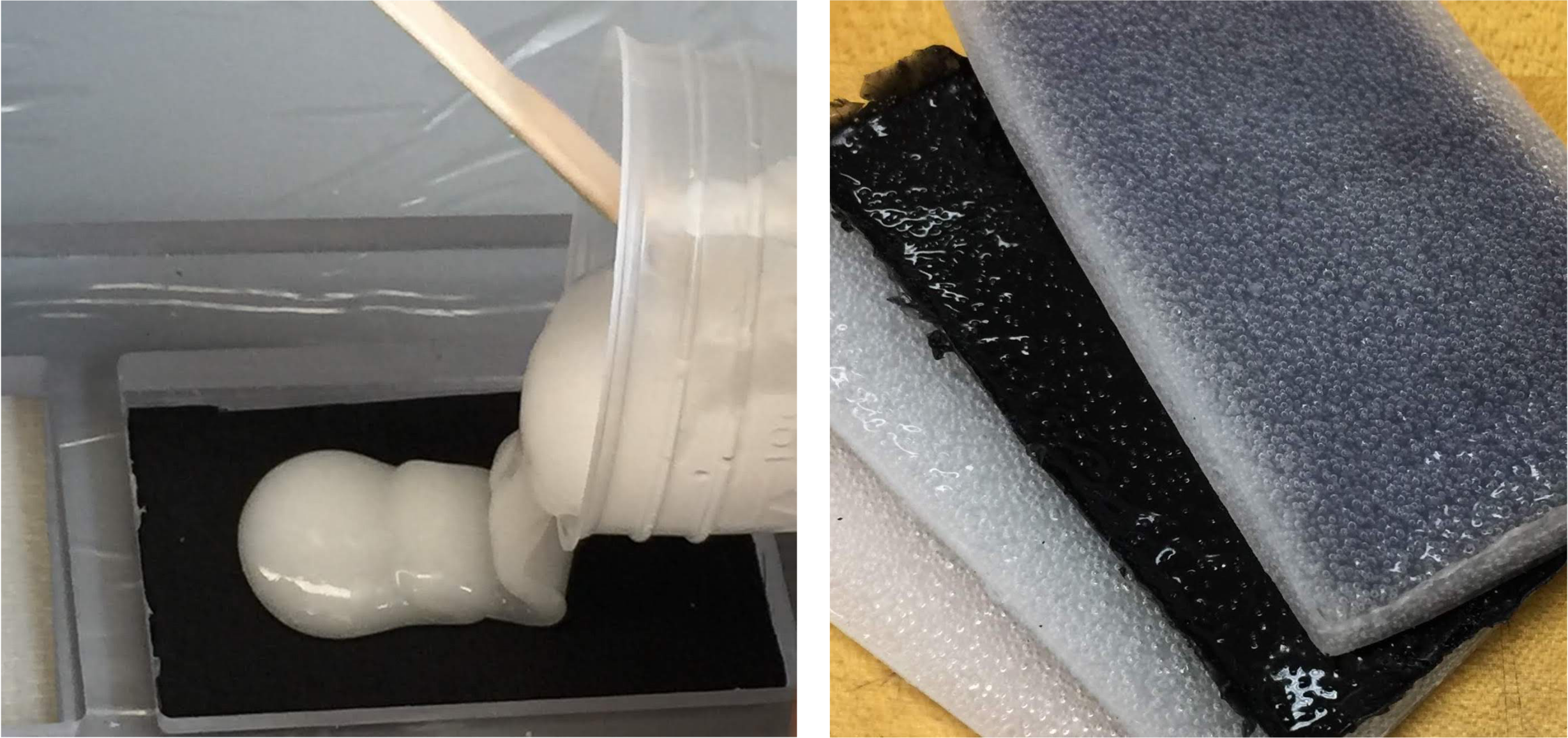
Samples of this material are prepared by mixing together two parts of an elastic silicone rubber with a fraction by mass of high concentration ethanol. After the sample has solidified within a few hours, it can be actuated by raising its temperature beyond the boiling point of ethanol, 78.4˚C. The sample expands in all non-constrained directions as the ethanol trapped within the silicone matrix evaporates, creating large pockets of trapped ethanol gas and air.
With access to large amounts of two-part silicone and ethanol, we set out to better undestand the functional characteristics of our material. To begin, I machined wells into a sheet of HDPE to serve as molds for our actuators (2.4”x4”). By experimenting with a number of different actuator compositions, we were able to determine the optimal ratio of ethanol to silicone that gave us the most dramatic actuation and greatest lifting force.
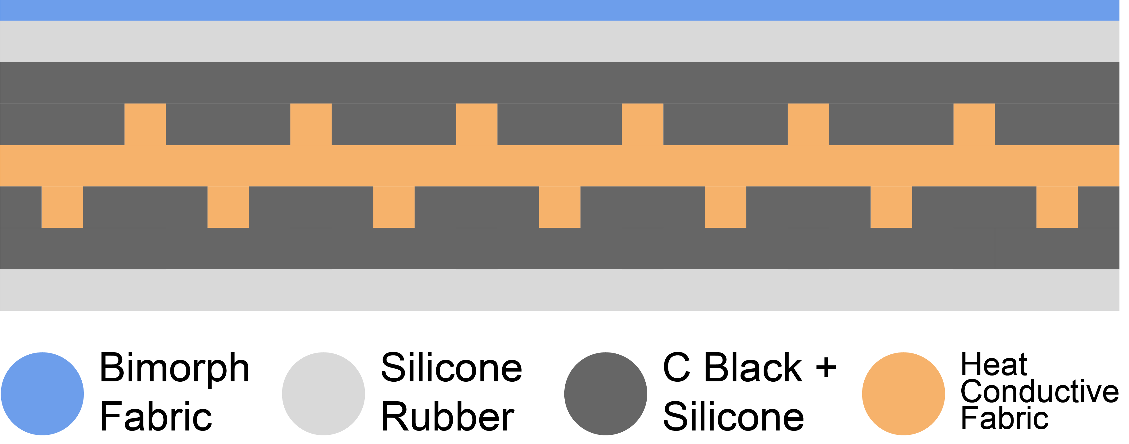
In our next set of material tests, we set out to strategically constrain our actuator’s expansion. We did this by fixing a mesh fabric to one of the large actuator faces so it would deflect (or curl) around the fabric as it expanded. This is known as bimorphic behavior, and it allows us to reliably lift things like solar panels over a well defined range of motion.
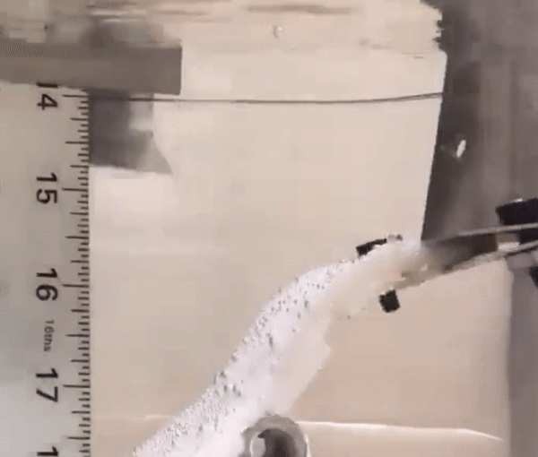
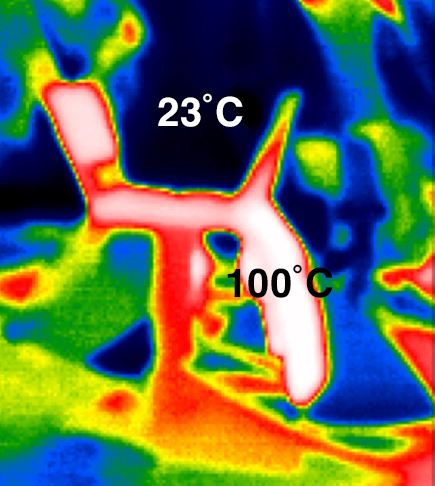
In order to ensure our samples were heating up as uniformly as possible during tests, we made good use of water baths with circulating heating units, to better understand the relationship between actuator deflection and temperature. In one such test, we were able to validate our actuators’ ability to repeatedly lift 5W solar cells over a wide range of motion.
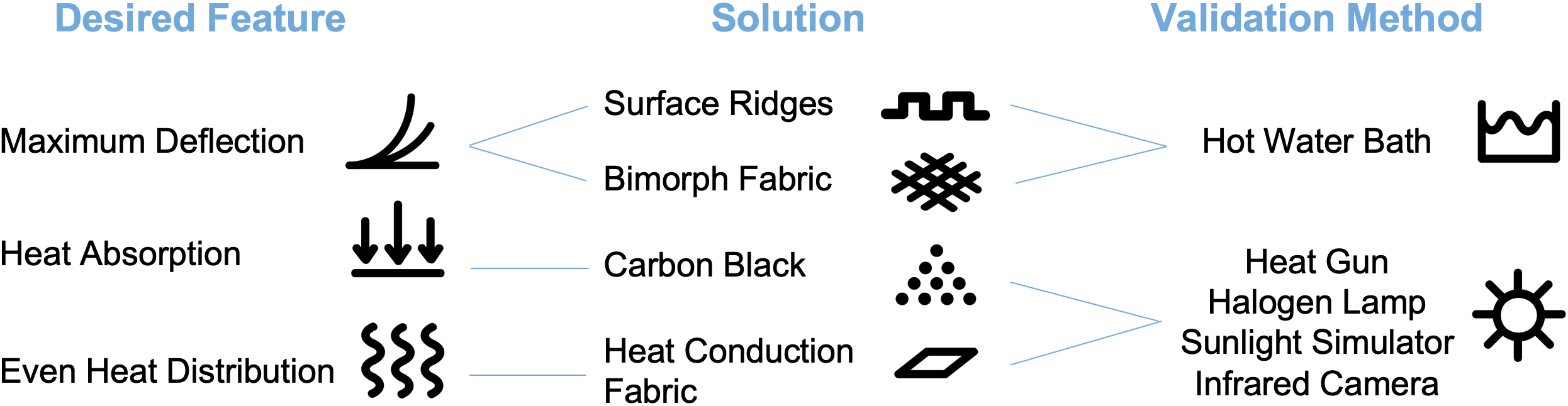
To conclude the material testing phase of our project, we worked to optimize both the composition and geometries of our soft robotic actuators to achieve the most deflection and lifting force with the least amount of sunlight (thermal energy). Along with the water bath, we used test configurations involving an electric heat guns, halogen lamps, and solar lamps (with spectral power distributions and power densities similar to the sun’s) to compare the expansion characteristics of our various actuator models.
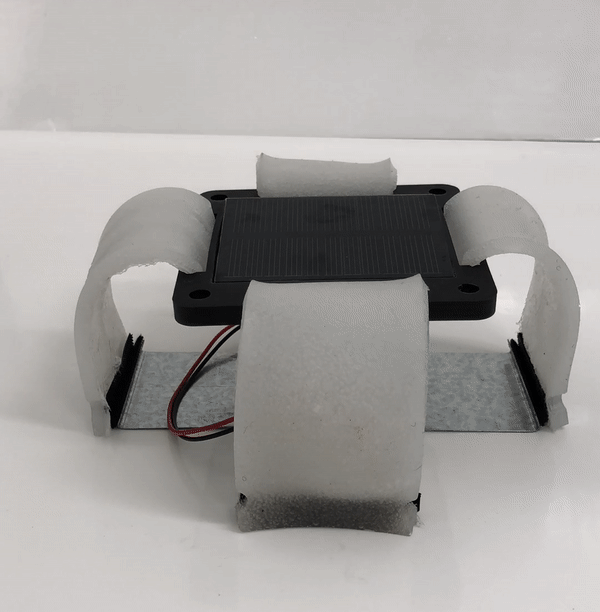
With a better understanding of how our actuators would behave in the sun, we built our first solar tracker prototype. We decided to include two opposing solar panels, so that when the device was aligned E-W, the sun (not accounting for changes in latitude or the earth’s axial tilt) would heat at least one ‘branch’ or actuator section to lift its respective solar panel towards the sun. From our material testing, we learned the sun’s power density (on any given Boston day) isn’t great enough on its own to properly heat our actuators. However, we included an array or mirrors to concentrate incident sunlight (and to increase the power density, W/m2) on the actuators. We also included a clear acrylic dome over our device to greatly reduce the conductive cooling felt during our outdoor tests.
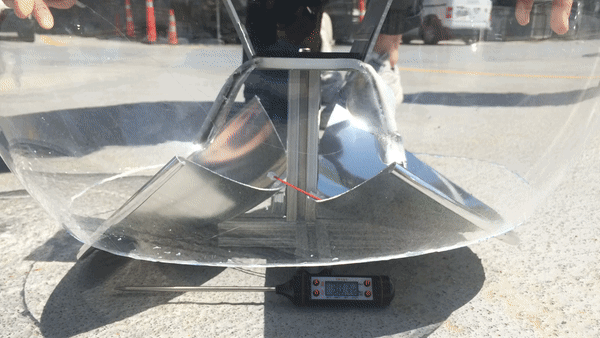
While actuation here isn’t dramatic, this test validates the sun’s ability to sufficiently heat our actuators. This also means that with further refinement, inexpensive soft robotic actuators have the potential to passively track ambient sunlight in order to increase the effectiveness and energy returns from standard PV cells.
With time to spare and more ideas for how to passively track the sun, we built two more prototypes. The first of these devices consists of three long, string-like actuators that support a single suspended PV cell. These actuators are contained in thin-walled copper piping, so that when one of these actuators is heated, it expands only lengthwise. Acting as independent pistons, the carriage and PV cell both orient themselves towards the sun as actuators warm up throughout the day.
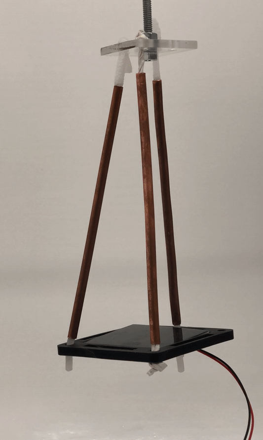
While this prototype worked well when actuated with a heat gun, engaging each ‘piston’ independently to track the sun in an outdoor setting is another challenge we didn’t have the chance to work through ourselves.
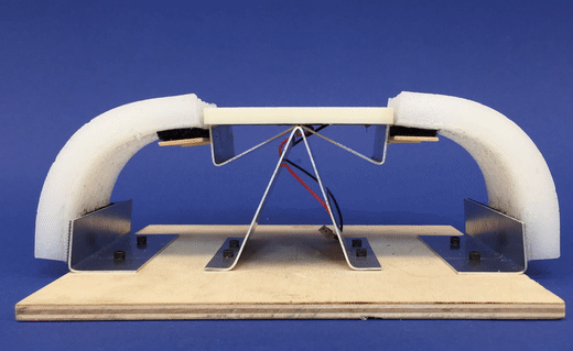
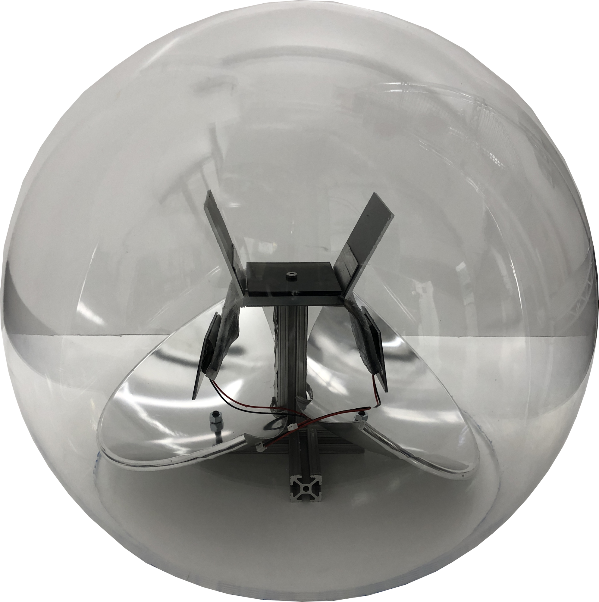
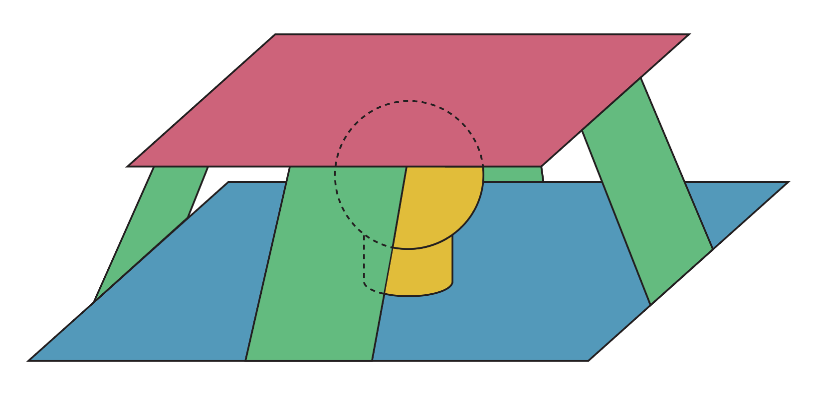
Our final prototype is a solar tracker that takes advantage of a fulcrum to reduce the force needed to orient a solar panel in one direction or the other. The PV cell rests in a plastic carriage that in turn rests on a golf ball to form a ball-and-socket joint. Four bimorph actuators curl pulling the carriage and cell in any of four directions (or a combination of the four) to achieve 2-axis passive tracking.
By the end of our year of capstone research, the four of us had designed and built three different solar tracker prototypes that served as proof that soft robotic components can be used to track the sun without expending electricity.
However, we felt we were still missing a fundamental understanding of how exactly the shape of our actuators affected their expansion. With free time during the summer between my senior year and grad school, I decided to continue where we left off in Prof Ranzani’s Morphable Biorobotics Lab. Over the next two months, I worked to better understand actuator expansion and force output as a function of geometry and temperature, in order to design a more effective, robust solar tracker modeled after our turtle design.
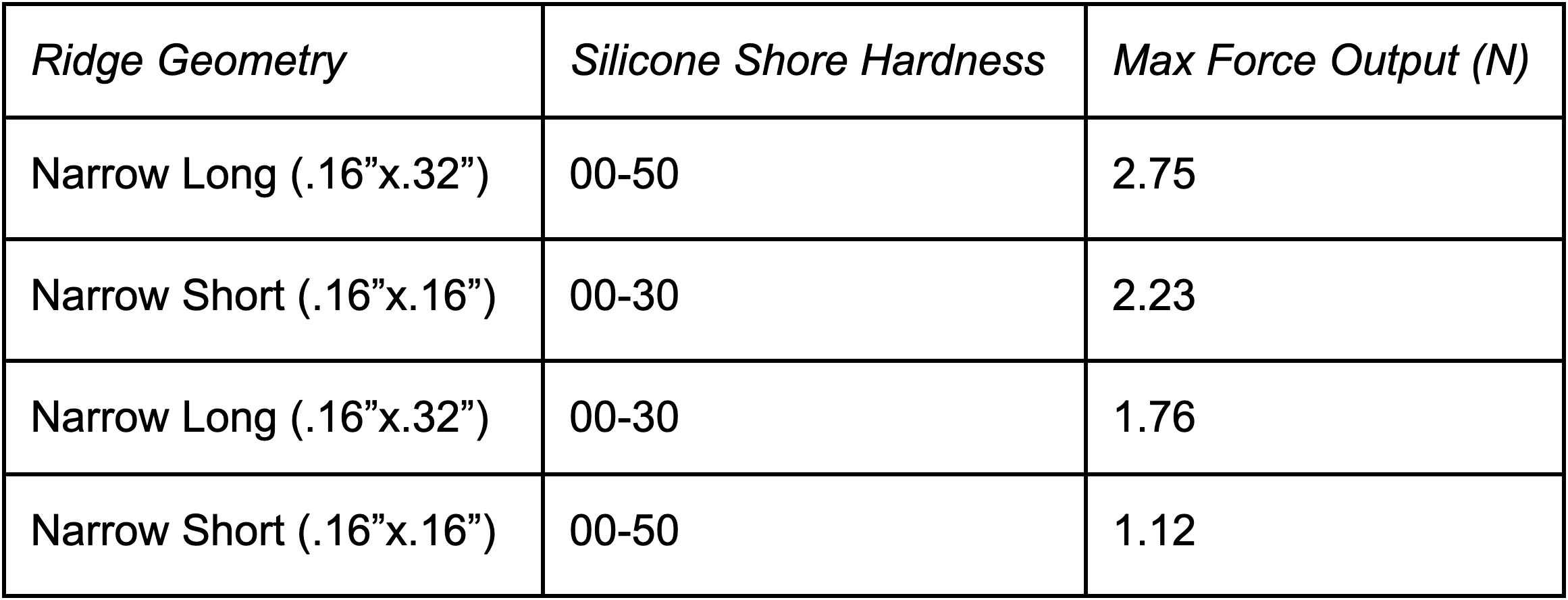
By varying parameters such as the type (notably the stiffness) of the silicone rubber, as well as the number and size of the vertical surface ridges that allow these actuators to curl up like a bimorph when heated, I was able to determine which actuators are best suited for solar tracking.
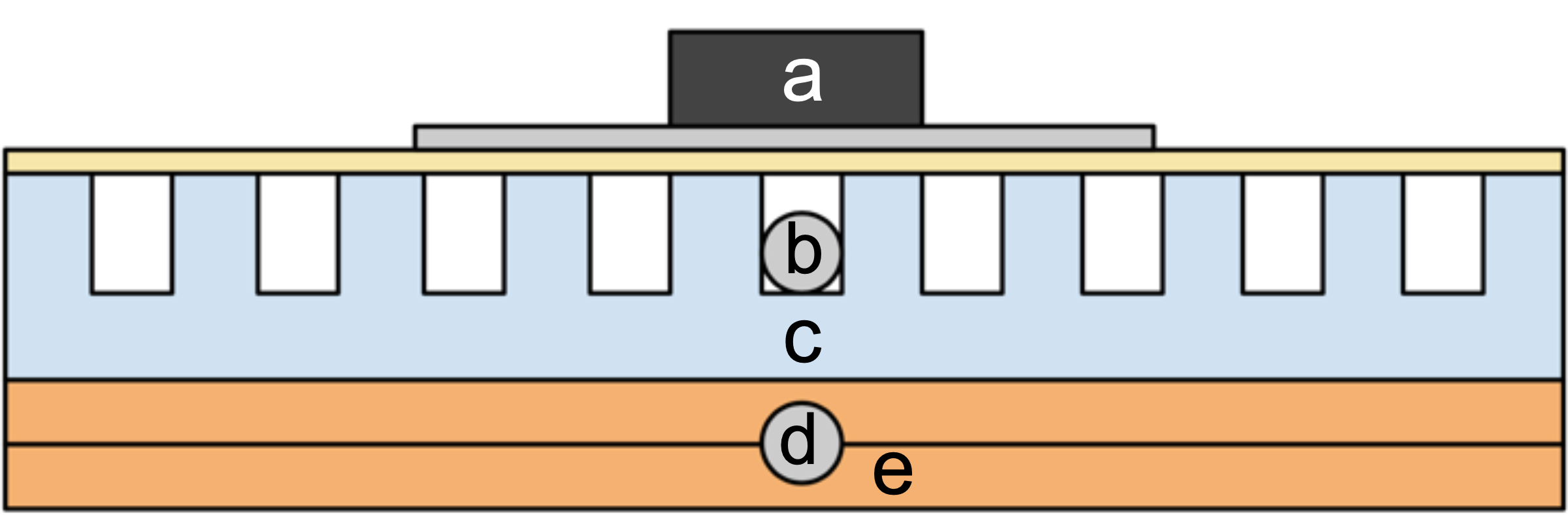
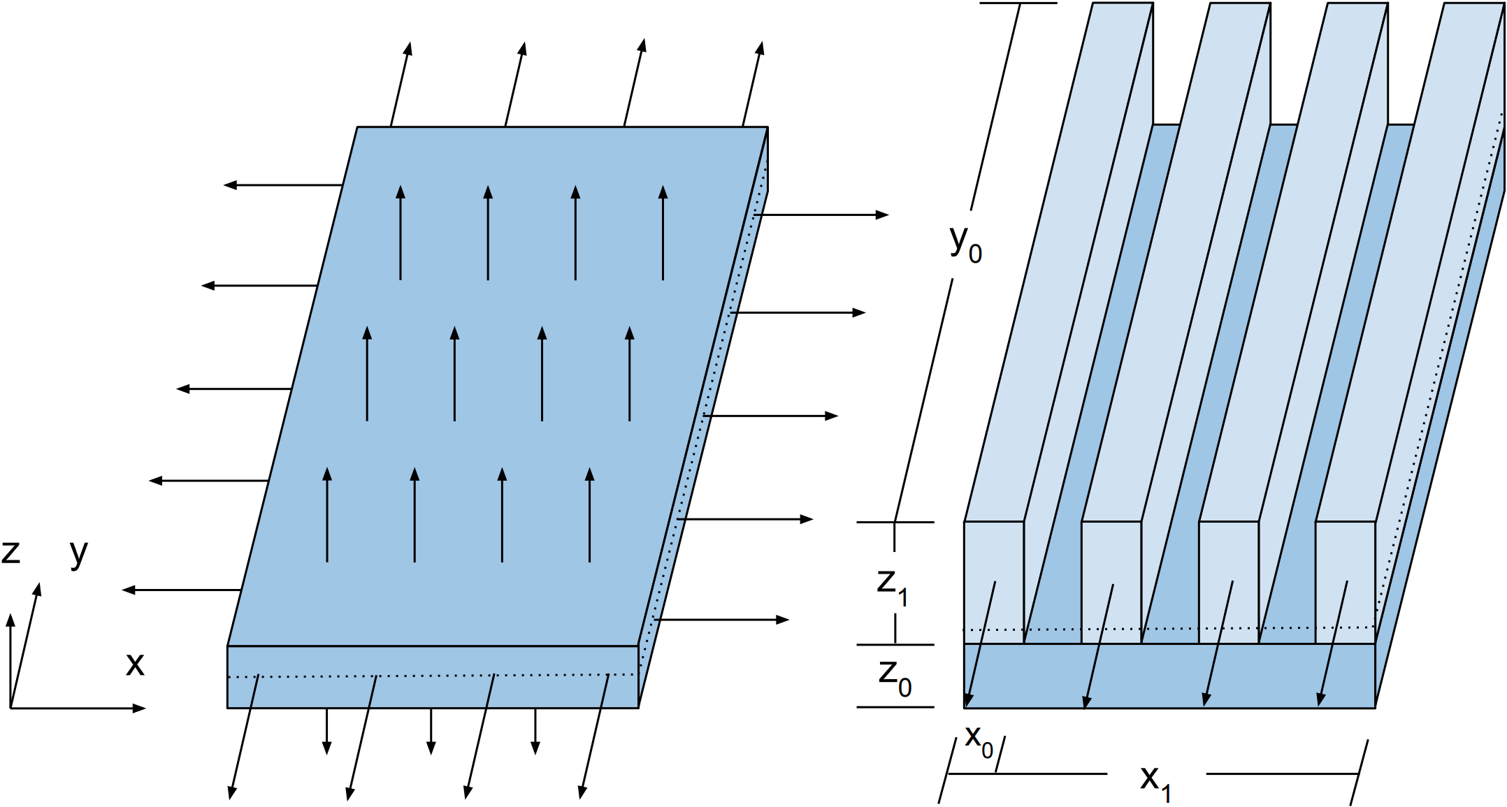
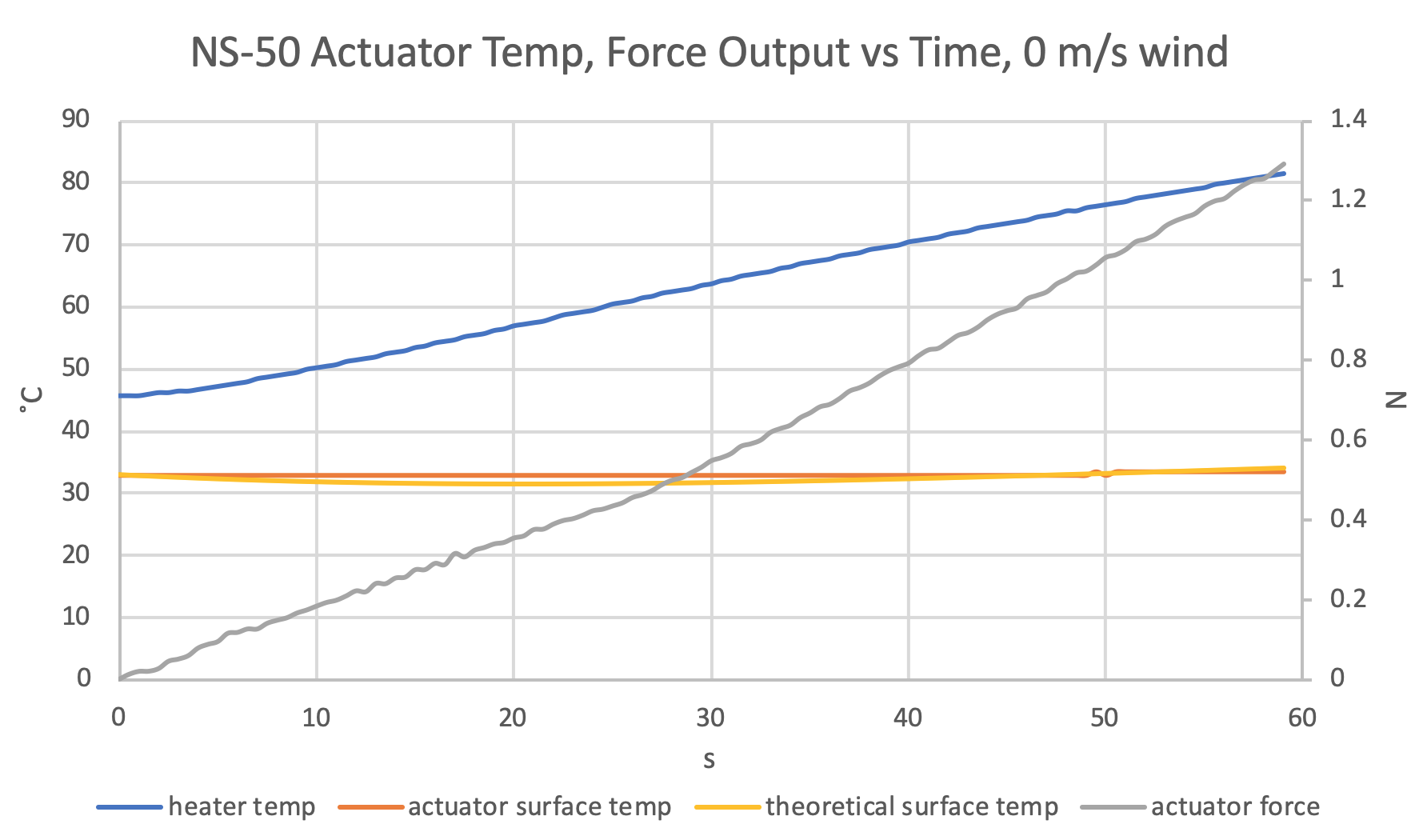
My main metric when refining the actuator design was force output as a function of temperature. This is essentially the force necessary to flatten a curling actuator as it's heating. This is an important relationship to understand, because it indicates the pulling force each actuator has on a solar panel given the current weather. To measure force, I built a blocked force testing configuration, where I heated a constrained actuator with a ohmic heating pad, and measured the force output with a load, as well as actuator and heater temperatures with k-type thermocouples. This allowed me to record force vs. temperature curves of actuators with various geometries and compositions.
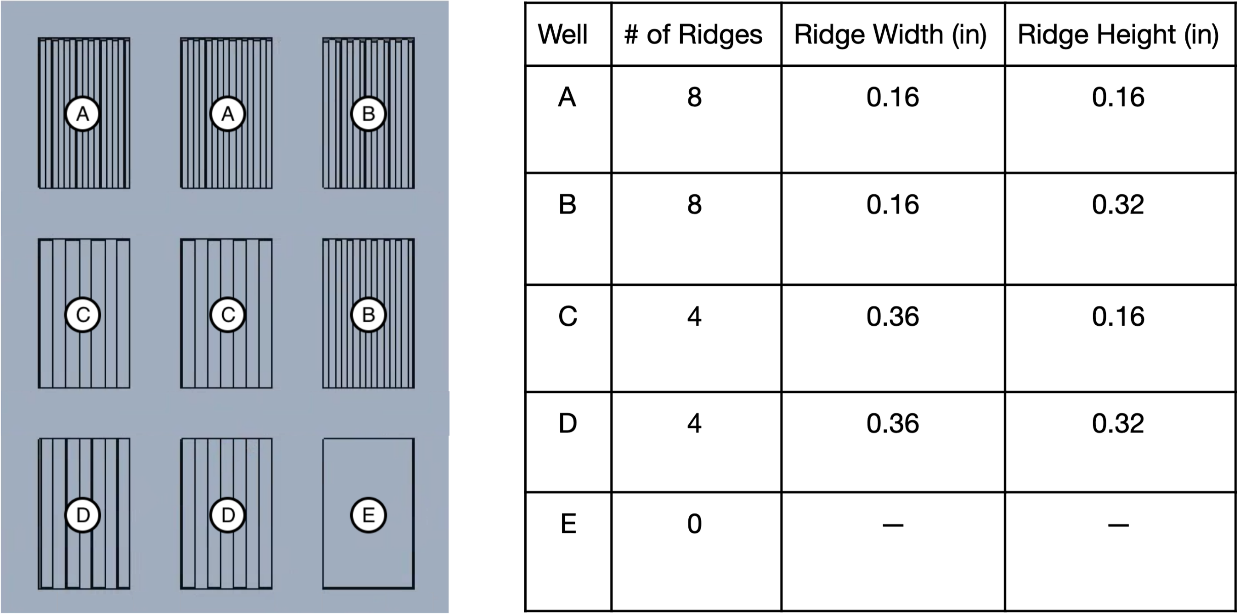
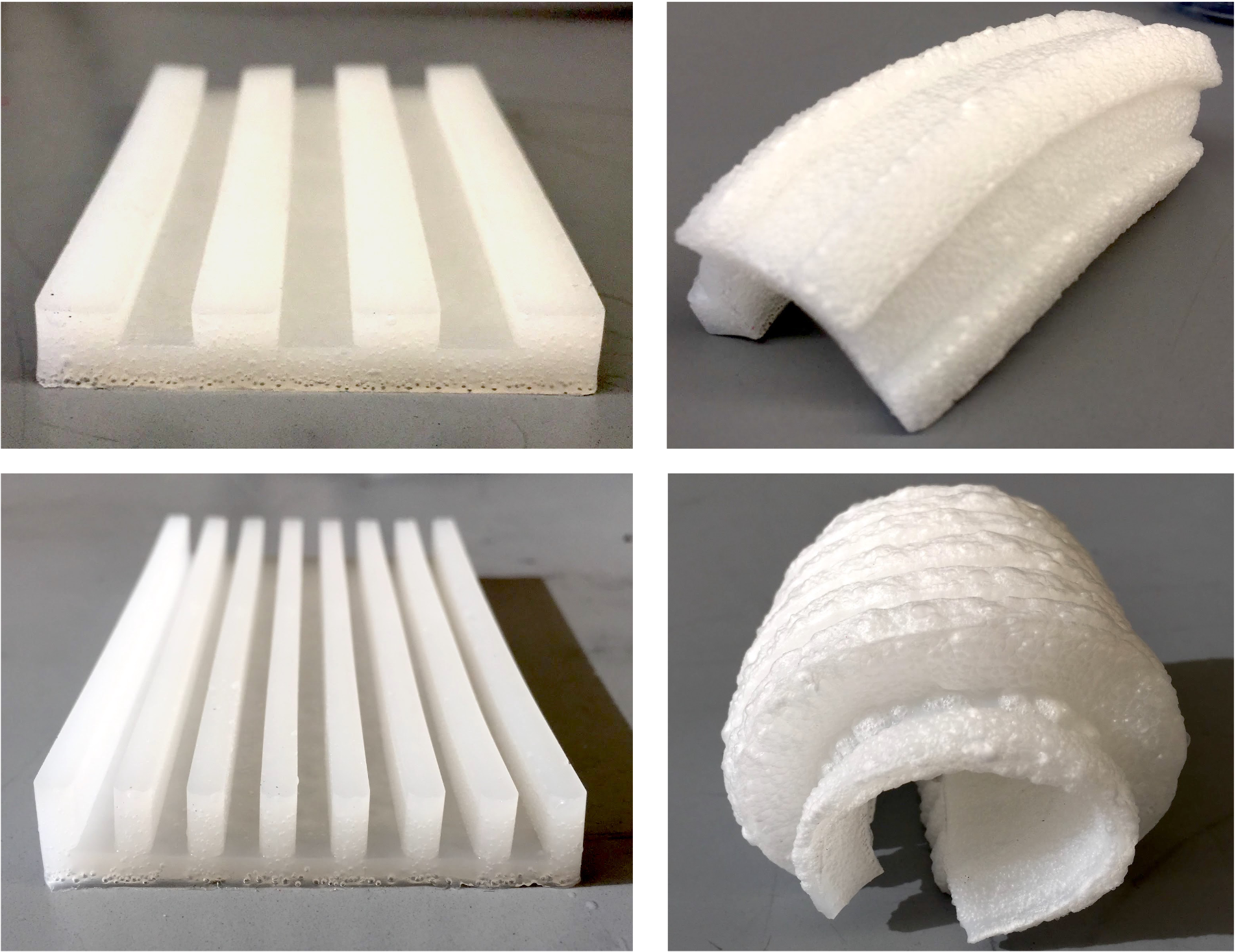
To create a set of standard, slightly varying actuators, I machined a set of well plates with ridges of various widths and depths. By pouring set amounts of silicone-ethanol mixtures, I had five distinct actuator shapes to start collecting data with.
I also heated each of these actuators with a heat gun to determine how they would deflect when unrestrained. Certain geometries were prone to lateral buckling, and were not used for further testing.
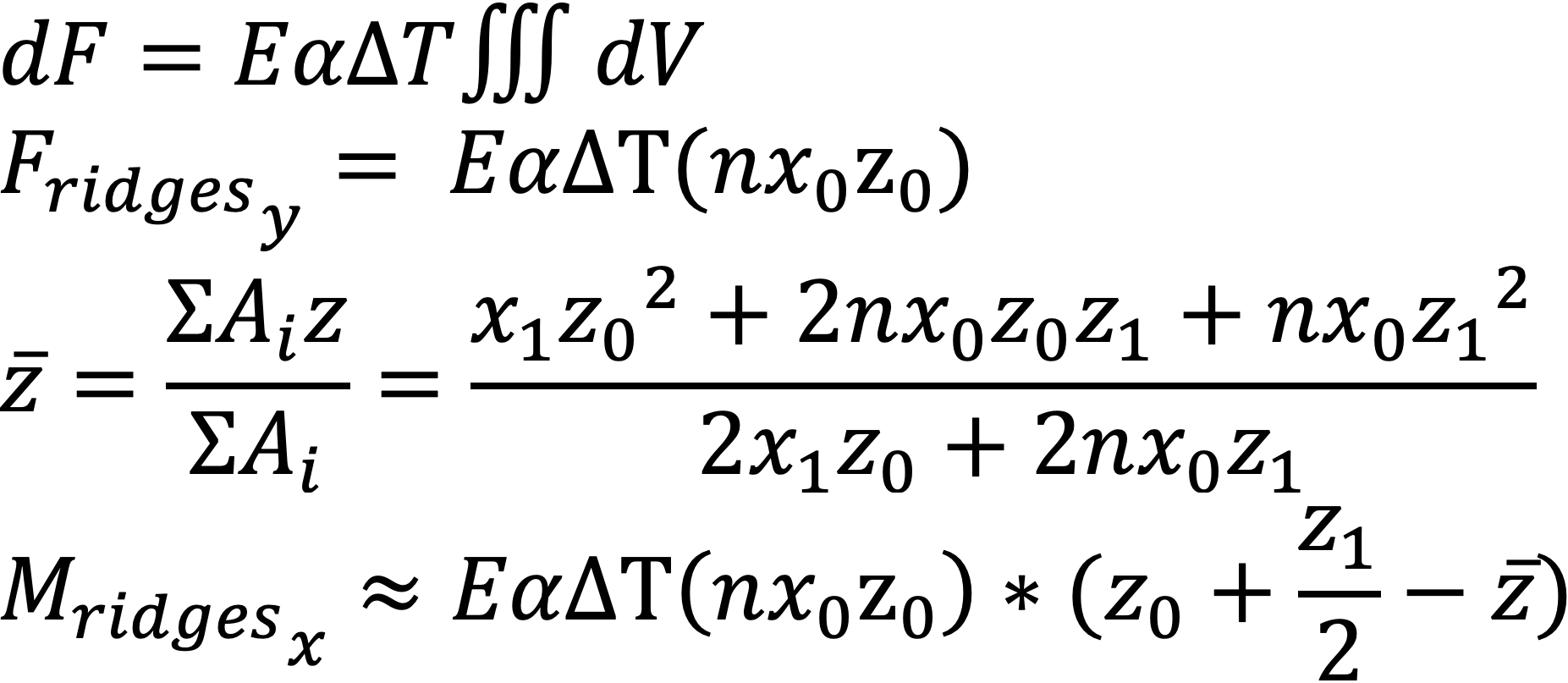
While I’ve yet to confirm this assumption with FEA simulations, I believe these actuators curl rather than expand in all directions because of a moment that results from the actuator’s vertical ridges. Microscopically, ethanol trapped in the silicone matrix expands in all directions as it begins to evaporate. Because the spaces between the raised ridges allow the ridges to expand freely in the x-direction, there is a net force that acts in positive and negative y-directions as expanding material pushes against adjacent material. If we assume based on its geometry that this force acts above the actuator’s neutral axis (dotted line, below), this force exudes a moment about the x-axis, bending the actuator about itself as it expands.
Despite ethanol’s well-defined boiling temperature, I was surprised to see how linearly a majority of the actuators expanded, as shown by their force output curves. I decided the actuator with narrow short ridges was the best suited for solar tracking because of how closely correlated its force output and temperature seemed.
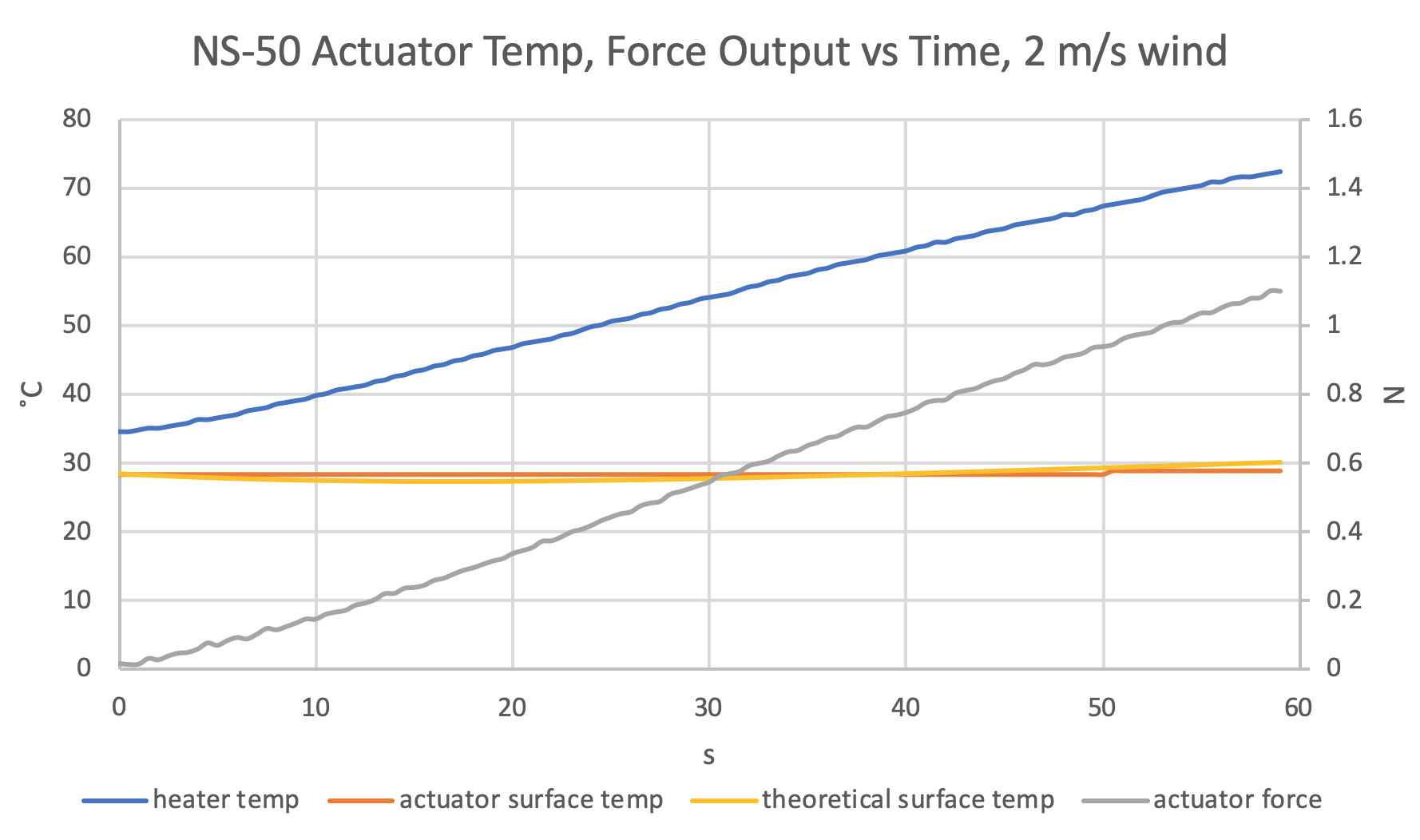
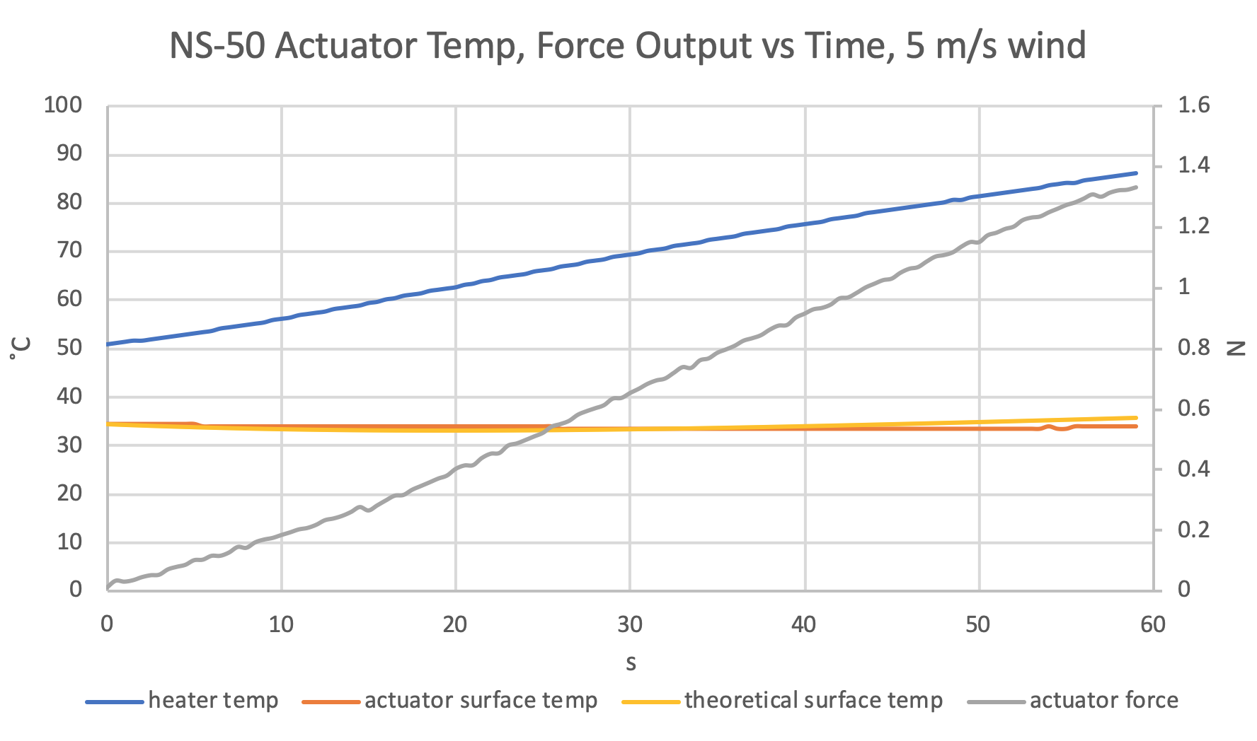
Finally, in order to get a sense of the effects of convective cooling on the relationship between actuator force output and temperature, I repeated blocked force testing in a wind tunnel at 2 m/s (a slight breeze, Re ≈ 64,800), and 5 m/s (mild wind, Re ≈ 162,000).
Before moving onto new research, I’d like to better understand the uncertainty of these force vs. temperature relationships, and would also like to investigate the relationship between actuator force/heater power density vs. the heat exchange coefficient, h.
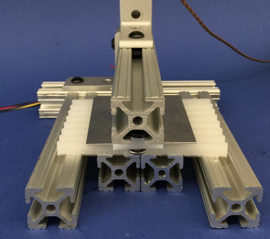
By the end of my summer research stint, I built a new single-axis solar tracker that uses the improved actuators I had designed. The tracker frame uses a metal fulcrum and light-weight model airplane hinges, so that little force is required for the actuators to pull the solar panel in the direction of the sun.
In the future, my research group and I—which has since grown include current BU students—look to quantify the effects of light alone on the actuation. To do this, we’re looking to measure actuator deflection as a function of light intensity in W/m2 by shining a focused LED array with a light spectral power distribution exclusive to visible light. With these results, we hope to publish a paper describing the potential for soft robotic materials to passively tracking ambient sunlight for improved solar energy collection.